Fourier Actuator Introduction
The physical quantities involved in the following description are defined in the table below.
| Symbol | Value | Unit | Description |
|---|---|---|---|
| Variable | Desired position | ||
| Variable | Feedback position | ||
| Variable | Position error | ||
| Variable | Desired velocity | ||
| Variable | Feedback velocity | ||
| Variable | Velocity error | ||
| Variable | Desired -axis current | ||
| Variable | Feedback -axis current | ||
| Variable | Desired torque | ||
| Velocity loop control period | |||
| Constant (determined by actuator model) | - | Current-to-torque conversion coefficient | |
| Constant (determined by actuator model) | - | Reduction ratio | |
| Constant (determined by actuator model) | - | Pole pairs | |
| Velocity conversion coefficient |
Control Mode Introduction
Current Mode

Velocity Mode

Position Mode

If the integral coefficient of the velocity loop is set to 0 in position mode, it is equivalent to Series PD.
PD Mode

Parameter Conversion between Position Mode and PD Mode
- Series parameters to parallel parameters (Position Mode --> PD Mode)
- Parallel parameters to series parameters (PD Mode --> Position Mode)
Other Actuator Features
PVCT Feedback Filtering
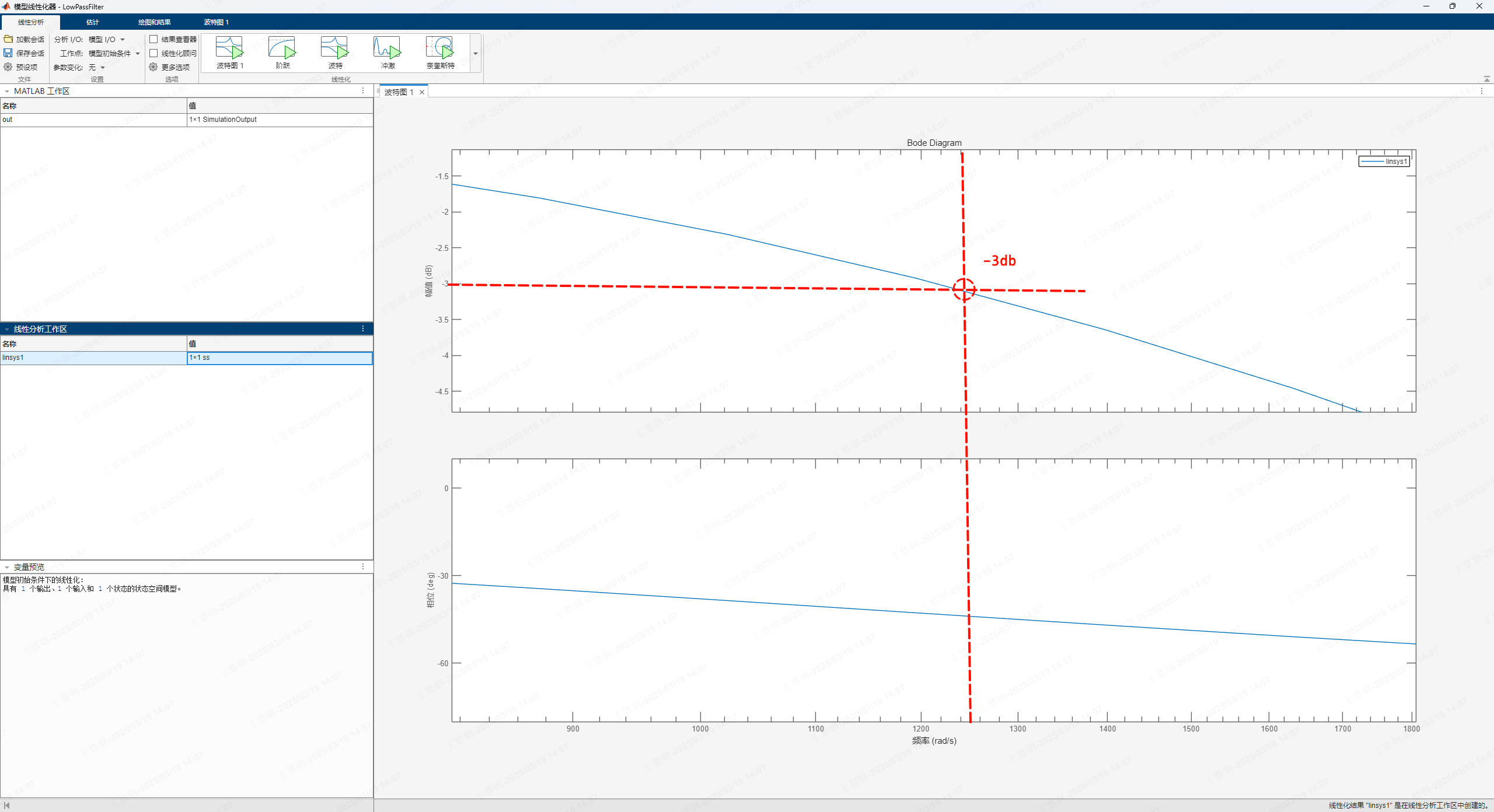
| Default Cutoff Frequency fc (Hz) | Gain | Period ts (s) |
|---|---|---|
| 200 (user adjustable) | 0.9409 (calculated from cutoff frequency and period) | 5e-5 (20KHz, same frequency as FOC) |
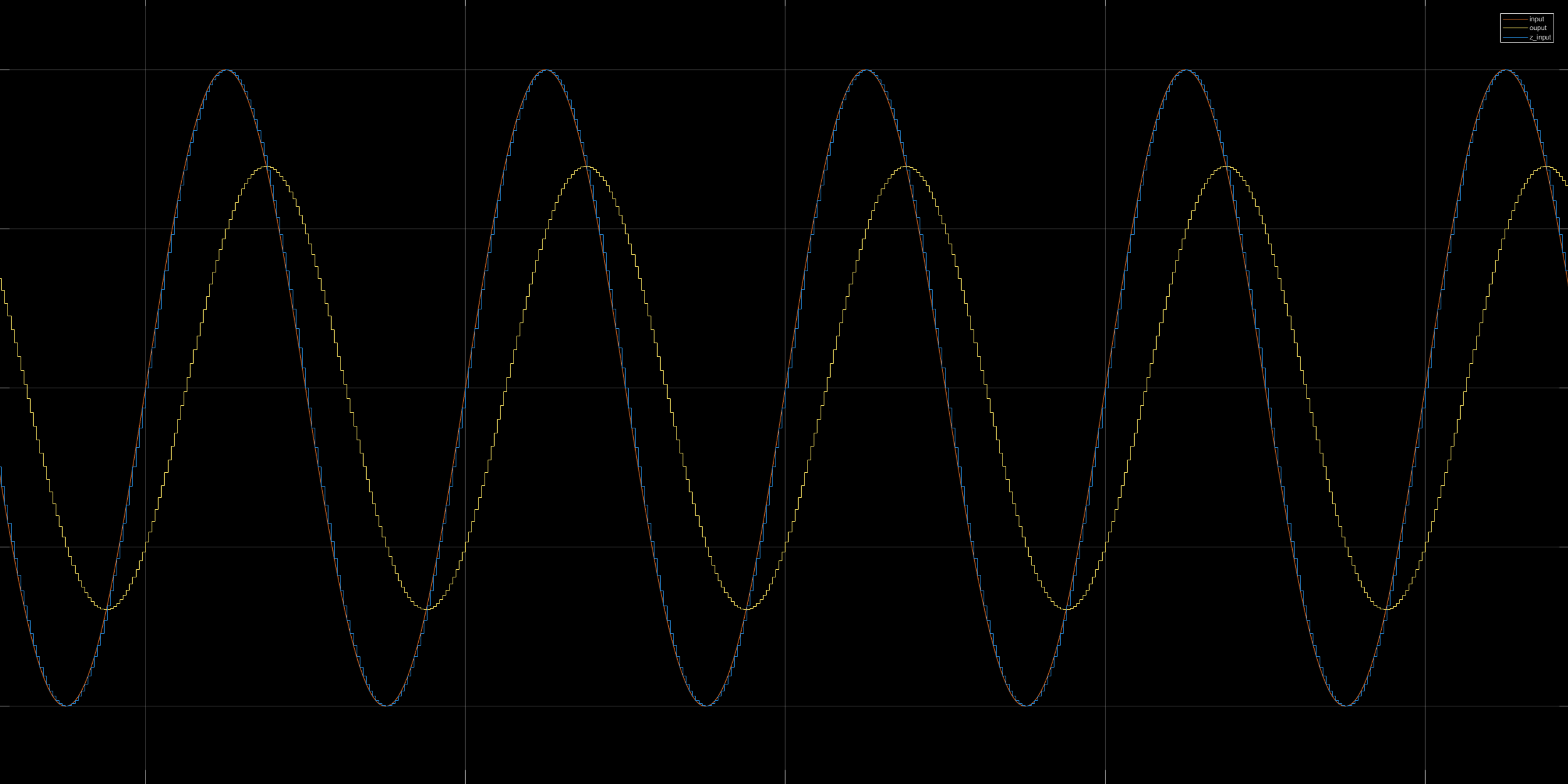
This filter will cause feedback data delay, so try not to add another filter in your user program, or set the filter cutoff frequency as high as possible to avoid impact.
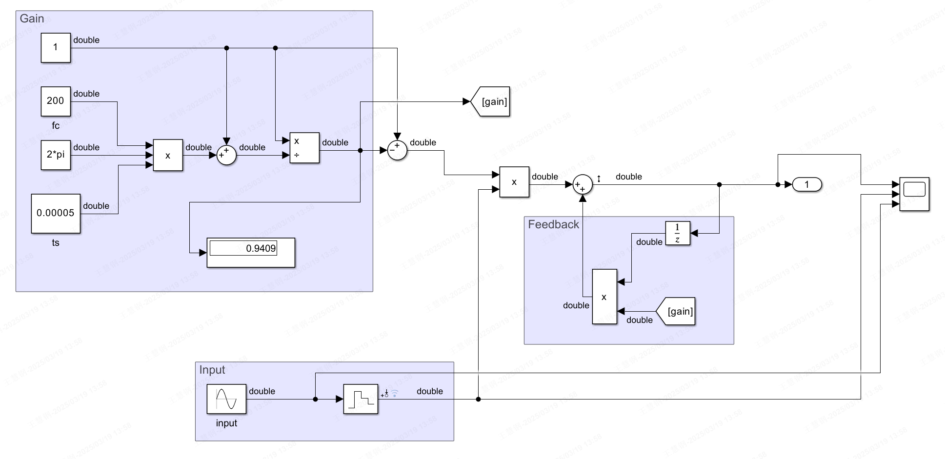
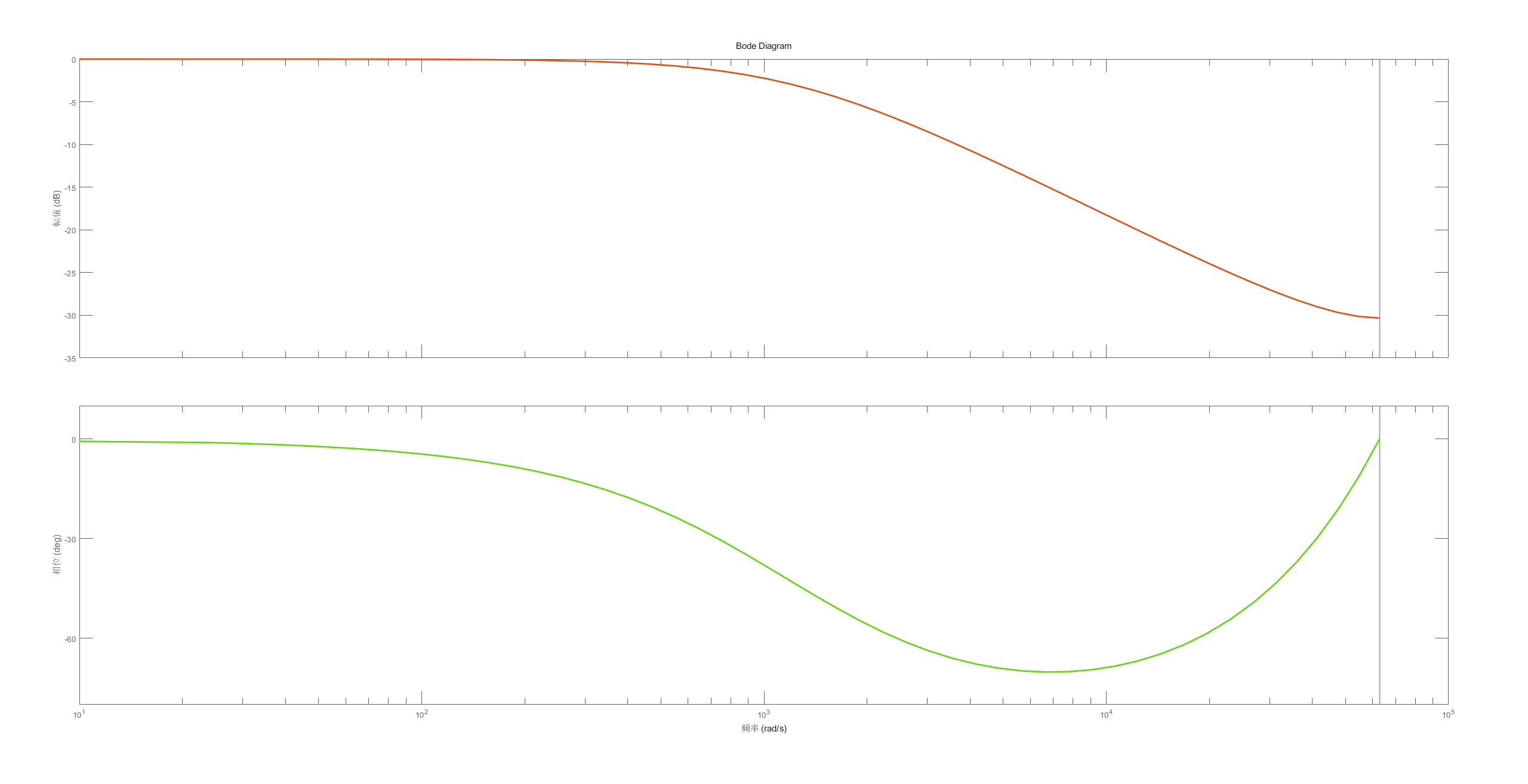
Input signal: 200Hz sine wave
Homing Mode
This mode is only available on FSA with dual encoders.
Homing mode uses the output shaft encoder data as position feedback (full closed-loop). Compared to using position mode to return to zero, homing mode can return to zero more accurately, avoiding zero position offset issues caused by reducer backlash and installation errors between internal and external encoders.

Friction Compensation
The friction compensation function can only be enabled after the actuator friction identification has been performed.
For friction identification, the actuator needs to be removed separately, and then the friction identification command is sent through the host computer. The actuator will automatically start identification, during which the actuator will rotate at high speed. After identification is complete, the obtained friction coefficients will be saved in the actuator.

Load Observer
After enabling load compensation, the low-speed performance of the actuator will be greatly improved. If the load compensation parameters are properly adjusted, very small velocity fluctuations can be maintained at extremely low speeds (below 1 deg/s).
